i've been tinkering with IBM tape unit terminators. the 729 tape units were…

Posted in
懷舊技術、產品
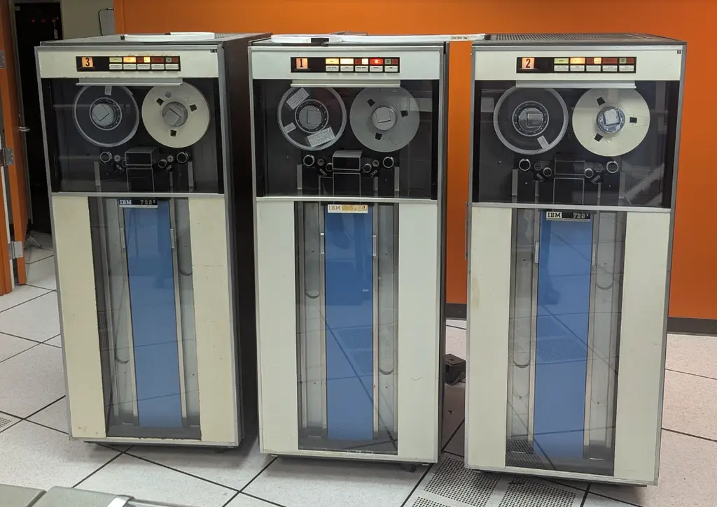
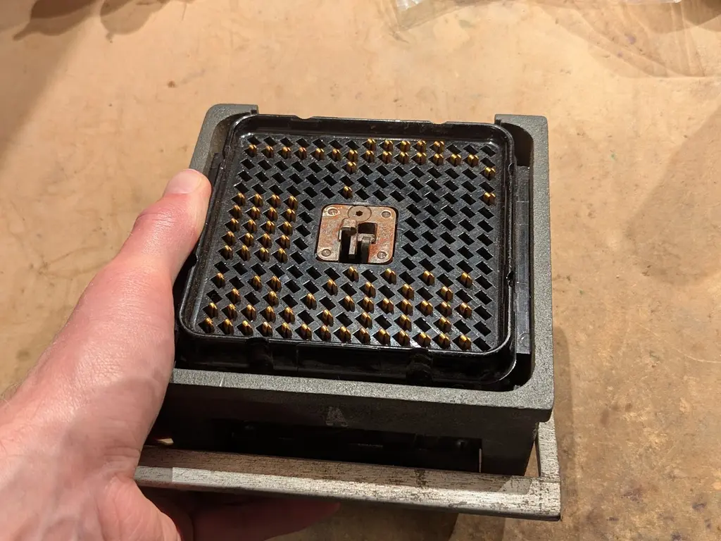
i’ve been tinkering with IBM tape unit terminators. the 729 tape units were daisy-chained and connected to a computer (such as the IBM 1401) but the end of the line needed this special terminator. it’s a giant waffle connector, same as used by the cables.
Comments (7)
(oh yeah, the picture of the tape units is somewhat special because we recently fixed all three of the 729 tape units on one of the Computer History Museum's two 1401 computers!)
inside a terminator is an array of resistors that are designed to connect a signal line (data or control) to a termination voltage with an impedance that matches the characteristic impedance of the coax that carries the signal. there are also 5uF capacitors that couple some of the coax shield lines to ground.
the official pinout looks like this. the upper section carries control and status lines. the right section has the tape unit select lines which assert when the computer wants to talk to a particular tape unit (matching the glowing number on the front panel). the left section has the read data bus, and the bottom section has the write data bus.
only signals that originate FROM the computer (and go out to all the tape unit) need the terminating network, which is just a 360 ohm and 120 ohm resistor (equivalent to 90 ohms, the coax impedance). signals from the tape units go into the computer and are terminated there.
this means that the terminator skips certain pins, notably the read bus--see that there are no pins on the left section--and the status signals (tape unit->computer) on the top section.
now what's weird is that the terminator has some EXTRA MYSTERY PINS that are not listed in any of the IBM 729 documentation. see the red box in this image.
@LapTop006 not really, they're easy to change because the glowing numbers are rotary switches. i was testing them individually and just landed on those numbers randomly.